Jeep Wrangler Forum banner

Install Synergy Suspension Ball Joints Write-up

75K views 53 replies 28 participants last post by  Giantrider  
#1 · (Edited)
Thanks to this forum, it didn't take me long to decide to ditch the crappy factory ball joints for something better: Synergy Suspension ball joints.
I tried to put the entire install in one thread but the site only allows a maximum of 15 images in a thread so I broke it down into 4 threads.


Vehicle

2011 Rubicon Unlimited


Tools & Supplies

2-3 pound hammer
Pair of jackstands
Floor jack
1/2" drive breaker bar
1/2" drive ratchet
1/2" drive extensions
1/2" drive 21mm socket
1/2" drive 13mm 12 point socket
Torque wrench
5mm allen wrench
Small flat blade screwdriver
7/8", 1-1/16", and 1-1/8" combination wrenches or sockets
5/16" socket or combination wrench
Diagonal pliers
Anti-seize
Wire Brush or Dremel
180 or 240 grit sandpaper
Ball joint press
Adapter set
Bungee cord or zip ties
Rubber mallet or deadlblow hammer
New ball joints
Brake cleaner
Rags
Extreme pressure moly grease


Notes

A. If you do this indoors make sure you allow at least 4 feet of space on the passenger side so you have room to remove the axle shaft and hub assembly.
B. The upper ball joint is pressed out/in from the top.
C. The lower ball joint is pressed in/out from the bottom.
D. I also installed axle tube seals at the same time.

Steps

1) Place the transmission in Park or 1st. Set the parking brake. Start on one side and loosen the wheel nuts. Raise the front of the Jeep and place a jackstand under the axle tube just inside of the axle 'C'.

2) Remove wheel/tire and set it out of the way.

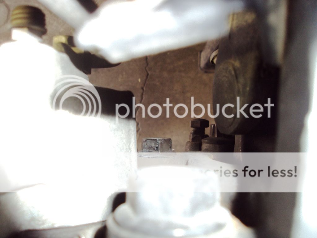
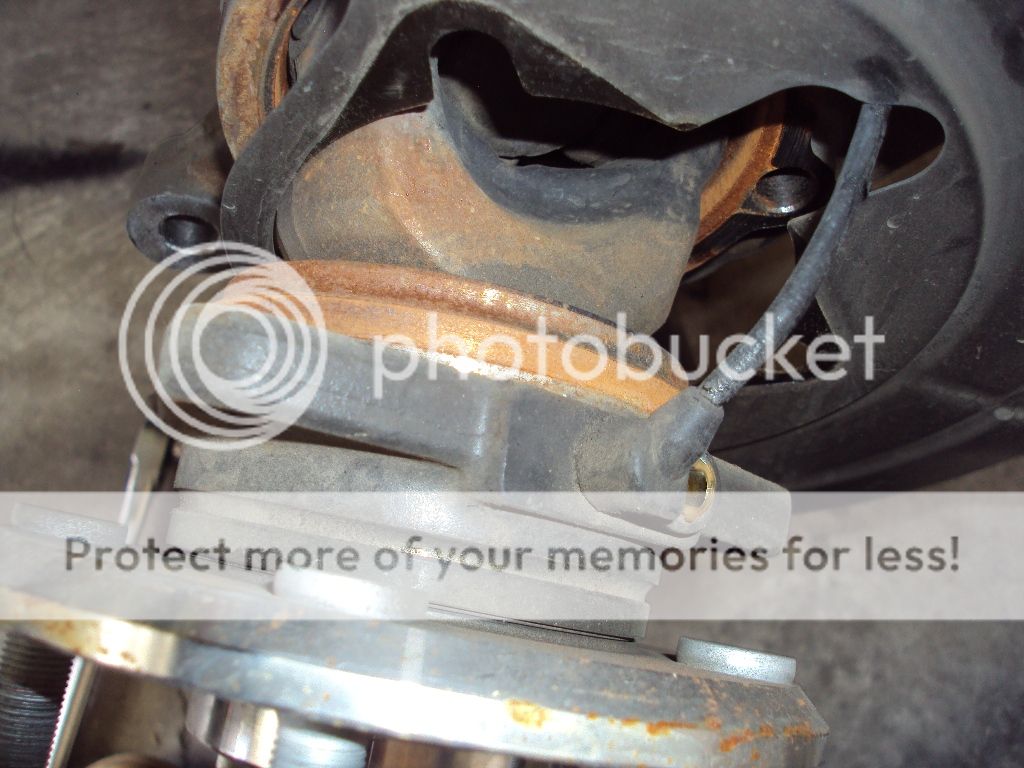
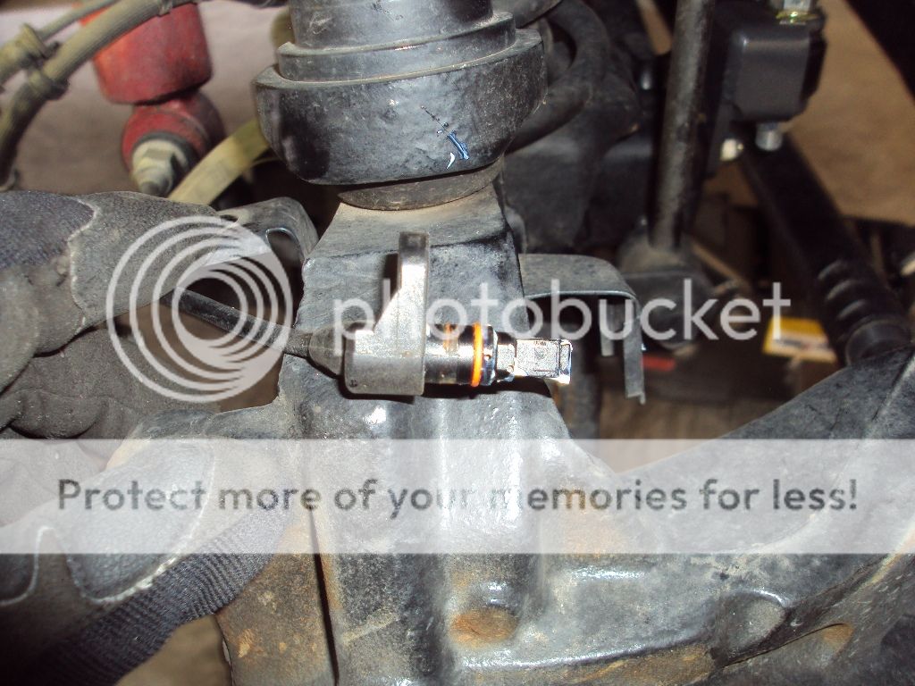
3) Unclip the wheel speed sensor harness from the brake hose and upper ball joint bracket.

Image


Image


Image


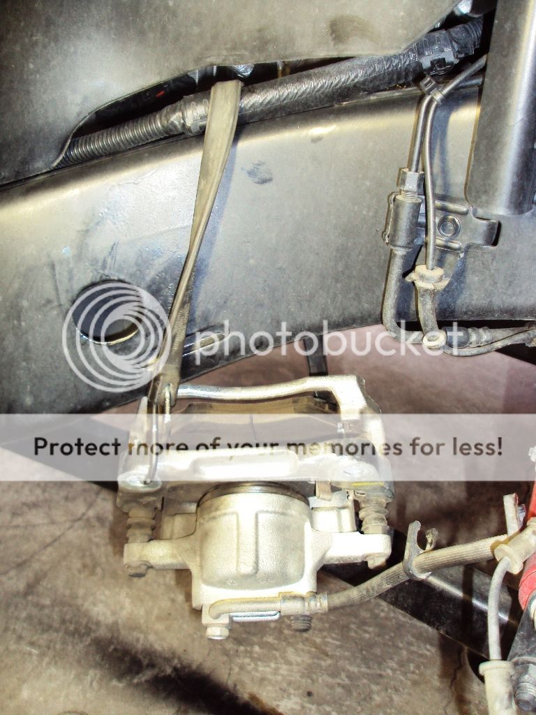
4) Remove the two 21mm bolts that hold the caliper assembly to the knuckle. Slide the caliper off the rotor and hang it from the frame with a bungee cord or zip ties. DO NOT LET THE CALIPER HANG BY THE BRAKE HOSE! Remove the rotor and set it aside.

Image


Image


Image


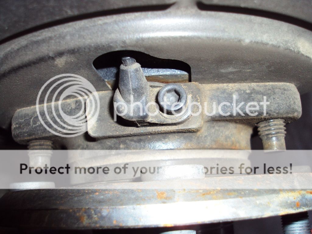
5) Remove the bolt that hold the wheel speed sensor to the hub bearing but do not remove sensor at this time.

Image


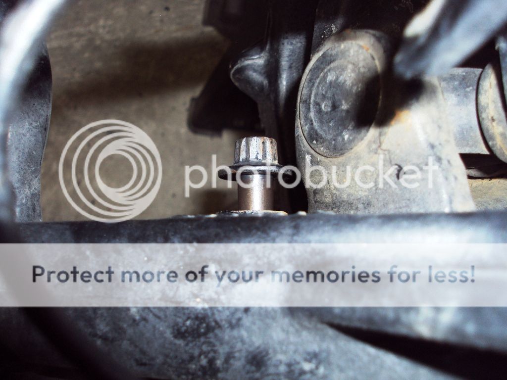
6) Using a 13mm 12 pint socket, remove the three bolts on the back side of the knuckle that mount the hub assembly to the knuckle.

Image


Image


7) Rap the outer edge of the hub assembly with a rubber mallet or deadblow hammer and pull it out from the knuckle a few inches.

Image


8) Carefully remove the wheel speed sensor from the hub and pass it through the slot in the backing plate. Hang the harness and sensor on the brake caliper. Treat the sensor gently as it can be easily broken or damaged.

Image


Image


9) Pull the axle shaft completely out and set it on a clean surface.

Image


Image


Image
 
#2 ·
Install Synergy Suspension Ball Joints Part 2

10) Pay attention to the plastic guides on the splined end of the axle. There are two of these. If one or both are missing, check inside the axle tube. If they slide off when removing the axle shaft, use a coat hanger or wire rod to fish them out an place them back on the splined end of the axle.

Image


11) Remove the cotter pin and upper ball joint nut.

Image


12) Remove the cotter pin and loosen the lower ball joint nut until only a few threads are left.

Image


13) Give the knuckle several sharp blows with the hammer to break it loose from the ball joints.

Image


14) Remove the lower ball joint nut; then remove the knuckle from the ball joint studs and swing it out of the way. Support the knuckle by placing a jackstand under the tie rod.

Image


15) Using the ball joint press and adapter kit, press the upper ball joint out of the axle 'C'. Tighten the press until the joint comes free. Periodically tap the area of the 'C' around the ball joint with the hammer. The vibrations will help the joint to press out.

Image


Image


Image


Image


Image


Image


16) Once the ball joint is loose, remove the press, adapter, and ball joint.

Image


Image

 
#3 ·
Install Synergy Suspension Ball Joints Part 3

17) Turn the press upside down and remove the lower ball joint.

Image


Image


Image


18) Clean the inside of the ball joint mounting holes with sandpaper or a wire brush and then wipe clean with brake cleaner on a rag. Apply a thin film of anit-seize to the inside of the holes.

19) Clean any dirt and debris from the inside of the axle tube. A vacuum cleaner with an extension wand works well for this.

Image


20) If installing axle tube seals proceed to Step 21. If not, skip to Step 23.

21) Using sandpaper or a wirebrush, clean any rust from the outer 2" of the axle tube. Wipe clean with brake cleaner on a rag. Apply a thin film of anti-seize to the inside of the axle tube.

22) Turn the axle tube seal so the grease fitting is facing to the rear and push it into the axle tube. If necessary, place a rag over the seal and use a hammer and block of wood to fully seat the seal in the end of the tube.

Image


Image


Image


23) Remove the boot from the Synergy Suspension lower ball joint by carefully pulling it free.

Image


Image


24) Using the press and adapter, install the lower ball joint until the lip is flush against the axle 'C'. MAKE SURE THE HOLE FOR THE GREASE FITTING IS FACING FORWARD AND ANGLED TOWARD THE AXLE 'C'!

Image


25) Install the dust boot on the lower ball joint by sliding it up the stud and seating the boot into the groove. Thread the nut onto the stud for safekeeping.

Image


26) Install the grease fitting into the ball joint. DO NOT OVERTIGHTEN!

Image


27) Remove the boot from the upper ball joint and install using the press and adapter.

Image


Image


28) Install the grease fitting and boot onto upper ball joint. The is very little clearance for the boot to seat inside the axle 'C' so use a small flat blade screwdriver to carefully push it into place.

Image
 
#4 ·
Install Synergy Suspension Ball Joints Part 4

29) Install the knuckle onto the ball joint studs and start the nuts.

30) Tighten the upper nut to 30 ft lbs.

31) Tighten the lower nut to 85 ft lbs. Then tighten the nut just enough to pass the cotter pin thru the hole. Bend the legs of the cotter pin to secure it in place.

32) Tighten the upper nut to 75 ft lbs. Then tighten the nut just enough to pass the cotter pin thru the hole. Bend the legs of the cotter pin to secure it in place.

33) Clean the area on the knuckle where the hub bearing mounts with sandpaper or a wirebrush. Clean with brake cleaner and a rag and apply a thin film of anti-seize.

Image


34) Clean the area on the hub bearing where it mounts to the knuckle with sandpaper or a wire brush and wipe clean.

Image


34A) If you installed axle tube seals, cut the plastic dirt deflector from the axle shaft and clean off the rust. Wipe clean and apply a film of wheel extreme pressure moly grease. Also remove the plastic guides from the inner end of the axle.

Image


35) Place the backing plate on the axle shaft and slide the axle shaft into the axle housing until the hub bearing is 2-3" from the knuckle.

36) Turn the axle so the wheel speed sensor mounting hole is on top. Guide the wheel speed sensor harness under the upper axle 'C' and thru the slot in the backing plate and put carefully put sensor into its' mounting hole.

37) Push the axle shaft fully in so the hub bearing and backing plate are flush against the knuckle. Line up the holes in the knuckle with the holes in the backing plate and hub bearing and install the three 13mm 12 point bolts. Torque the bolts to 70 ft lbs.

38) Clip the wheel speed sensor harness back to the upper ball joint bracket and brake hose.

39) Install the speed sensor mounting screw and tighten to 34-50 inch pounds.

40) Slide the brake caliper back over the rotor and install the caliper bolts. Tighten to 120 ft lbs.

41) Install wheel/tire and torque the wheel nuts to 95 ft lbs.

42) Remove the jackstand and lower the vehicle.

43) Grease the ball joints until the boots begin to unseat from joints. Re-seat the boots and wipe off the excess grease.

44) Go for a short test drive and make sure the ABS light doesn't come on.


#46 ·
29) Install the knuckle onto the ball joint studs and start the nuts.

30) Tighten the upper nut to 30 ft lbs.

31) Tighten the lower nut to 85 ft lbs. Then tighten the nut just enough to pass the cotter pin thru the hole. Bend the legs of the cotter pin to secure it in place.

32) Tighten the upper nut to 75 ft lbs. Then tighten the nut just enough to pass the cotter pin thru the hole. Bend the legs of the cotter pin to secure it in place.

33) Clean the area on the knuckle where the hub bearing mounts with sandpaper or a wirebrush. Clean with brake cleaner and a rag and apply a thin film of anti-seize.

Image


34) Clean the area on the hub bearing where it mounts to the knuckle with sandpaper or a wire brush and wipe clean.

Image


34A) If you installed axle tube seals, cut the plastic dirt deflector from the axle shaft and clean off the rust. Wipe clean and apply a film of wheel extreme pressure moly grease. Also remove the plastic guides from the inner end of the axle.

Image


35) Place the backing plate on the axle shaft and slide the axle shaft into the axle housing until the hub bearing is 2-3" from the knuckle.

36) Turn the axle so the wheel speed sensor mounting hole is on top. Guide the wheel speed sensor harness under the upper axle 'C' and thru the slot in the backing plate and put carefully put sensor into its' mounting hole.

37) Push the axle shaft fully in so the hub bearing and backing plate are flush against the knuckle. Line up the holes in the knuckle with the holes in the backing plate and hub bearing and install the three 13mm 12 point bolts. Torque the bolts to 70 ft lbs.

38) Clip the wheel speed sensor harness back to the upper ball joint bracket and brake hose.

39) Install the speed sensor mounting screw and tighten to 34-50 inch pounds.

40) Slide the brake caliper back over the rotor and install the caliper bolts. Tighten to 120 ft lbs.

41) Install wheel/tire and torque the wheel nuts to 95 ft lbs.

42) Remove the jackstand and lower the vehicle.

43) Grease the ball joints until the boots begin to unseat from joints. Re-seat the boots and wipe off the excess grease.

44) Go for a short test drive and make sure the ABS light doesn't come on.


i did this when i install my 4.88 gears:punk::punk::punk:
 
#13 ·
is there a way to make this all one post, Im gonna go look for the other 3 parts now, great job!!! thank you
 
#15 ·
Write up was a great help..... Thanks.

We had to deal with missing pieces from the Advanced ball joint kit I rented. We made do :p
Broke a wheel sensor :eek:
Hopefully getting a replacement from Napa.
Drives a little stiffer but read it takes some miles to work the new joints in.

Did not have time to do the tie rod ends I had planned also :(

Thanks again :thumb:
 
#17 ·
SilverRubi said:
Glad the writeup helped. Yeah the wheel sensors are fragile, but at least they don't cost an arm and a leg. :)
:wavey:

Ya-we were so careful and it still broke.

Is that true what I read, taking some miles for things to loosen up? Rides a little tight but overall better.
 
#18 ·
kjeeper10 said:
Write up was a great help..... Thanks.

We had to deal with missing pieces from the Advanced ball joint kit I rented. We made do :p
Broke a wheel sensor :eek:
Hopefully getting a replacement from Napa.
Drives a little stiffer but read it takes some miles to work the new joints in.

Did not have time to do the tie rod ends I had planned also :(

Thanks again :thumb:
Glad you got it done!
 
#19 ·
I greased mine really well (until grease oozed out of the boots), then wiped off the excess and pushed the boots back in place.

Steering seemed a tad bit tighter, but in a good way! :thumb:
 
#24 ·
They are greasable for longer life and they dont have the cheap plastic liners. They are built more heavy duty.


:D Wonderful writeup--

I grease mine each oil change, along with the LCAs and you just have to be careful you don't inject TOO MUCH, at least in the ball joints !!

:dance::rofl: JIMBO
Thanks Jimbo,

I used to think a little grease would go along way. I called Synergy and spoke to a tech. He recommended pumping grease into em until the grease pooped out of the boot, then wipe off excess and reseat boot. :whistling:

Forgot to ask.

What's up with the top ball joint on our Jk.
Not really a "ball joint" is it ?

They don't seem to move all around like the bottoms :confused:
The uppers are designed for only vertical movement.
 
#25 ·
:D Well I can't agree with the Syn tech, ain't no way I'm over greasing and then RE-SEATING the boot--

Been greasing "booted" zirk suspension too many years to UNSEAT the boots--with a hand op grease gun, it's easy to be "JUST RIGHT", but when they use a powered grease gun--BAM !

The bottom ball joint supports the majority of the jeep weight and the top one also determines the CAMBER of the knuckle !

Lotta stress/forces on those little suckers !

Again, great write up silver !

:dance::rofl: JIMBO
 
#27 ·
Until now, I always felt the same way as Jimbo concerning greasing suspension components featuring boots. Just a few pumps with a hand gun until the boots started to expand and all was good.

I am also used to seeing boots with a metal retaining ring around the top. They arent made to easily unseat.

The Synergy boots are different tho. The top of the boot has a lip inside the boot that fits a groove on the ball joint. Easy to pop back on.

But to each his own. Even if you don't agree with Synergy's logic, the joints still need to have some grease added every oil change.